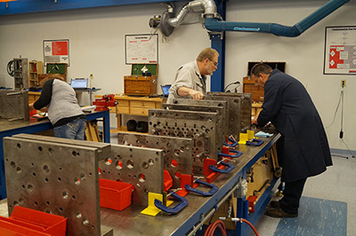
How to Become a Tooling Troubleshooter, Not a Tooling Replacer
courtesy of ToolingDocs
When a mold has to be repaired due to excess flashing on a part, technicians usually try to get the job done
as quickly as possible so the mold can go back into production. Many times, that solution works and the
repaired mold runs at 100% efficiency. But in repairing the mold, did the technician simply replace tooling
which might not yet have been at the end of its useful life? If so, was the old tooling thrown out, or was
it tossed onto a shelf or into a cabinet?
That’s where troubleshooting comes in, which is a lot different that just replacing a mold.
Technicians who are skilled at troubleshooting understand how their molds function. They pay attention to
the details that could make a big difference at their shop. They consistently follow proven troubleshooting
techniques, and use historical data at their shop to guide tooling replacement decisions.
Below are proven troubleshooting techniques for repairing molds that have part defects, such as flash.
They’re based on the same procedures you probably follow now, with a little more detail to ensure
that you’re troubleshooting – not just replacing – components of the mold. As a result,
you can save your company a significant amount of money by not replacing tooling before it’s at the
end of its useful life.
How technicians usually repair molds
First lets look at the typical process that technicians who are “tooling replacers” usually
follow. Let’s assume that, according to their Work Order, the technician has disassembled a
multi-cavity mold and then indicated locations where flash falls over the spec limit on the cavity
layout sheet.
Their next steps usually include:
Examining defect samples to determine exact flash locations;
Determining which piece of tooling (core, sleeve or cavity) caused the flash;
Removing and examining tooling areas forming the flashed area of the part;
If nothing obvious is found, looking in the tool crib for the tooling that may have caused the
damage;
Measure the tooling, compare their measurements to print tolerances and then replace tooling if
measurements are under print specifications (NOTE: For many shops, this step is mandatory)
Installing the replaced tooling in the mold and completing the repair.
How tooling troubleshooters repair molds
Now let’s look at the steps that a tooling troubleshooter would take to determine the root
causes of flashing to ensure that proper corrective actions can be taken:
Examine defect samples to determine the exact location AND
direction of the flash – Knowing the direction of the flash will help you
identify its root cause and correct the problem. For example, a vertical flash is usually
caused by too much plastic between a core and sleeve or other tooling (where clearance is
determined by a running fit). If the flash is horizontal, it’s usually due to excess
plastic between two shutoffs (the “A” and “B” plate cavity faces, for
example). It can also be caused by excess plastic between tooling where preload (total tooling
stack) or clamp pressure and other shut-off factors affect clearance.
Determine which piece of tooling (core, sleeve, cavity)
caused the flash – Parts that are more complex and difficult to eject
from the mold typically require more tooling. However, not all pieces of tooling will be worn
to the point of causing the flash. To figure out which one caused the flash, record and track
defects by mold position and look for patterns or trends caused by insufficient cooling,
heating, runner/flow balance, gate or venting issues, and other process-related root causes.
Mold position numbers never change and should be stamped, etched or ground onto plates and
tooling so that everything gets reassembled in its correct “home” position.
Remove and examine tooling that forms the flashed area of the part – This
is a great example that differentiates tooling troubleshooters from tooling replacers.
First, if two or more parts (positions) have the exact same defect,
it’s best to examine all tooling at the same time rather than analyzing and
correcting defects while going around the mold in a clockwise fashion.
Second, use your micrometer to measure the tooling but don’t assume
it’s bad if it’s under print dimensions. Many tooling components that are 0.001
- 0.003 under print tolerances make perfectly acceptable parts. Print tolerances should be
a factor in replacement decisions, not the deciding vote.
Third, develop a standard method to examine tooling; for example:
Remove suspect tooling from the mold after making sure that each piece
is numbered with its mold position number;
Get a matching piece of new or replacement tooling from the tool crib;
Bring part defects with the old and new tooling to your high quality
stereo microscope;
Orient tooling in the way it should fit in the mold;
Set the scope’s power to 10 (or more if micro-molding); anything
over that amount can make a good running fit look like it should cause flashing;
Compare the mated tooling to the flash area on the part, being aware of
flash direction, length and thickness. After you identify which piece is flashing, make
a mental note of the clearance between tooling. Replace that piece with new tooling and
recheck the clearance to see if it’s the same or less. If it’s a dynamic
fit (core or sleeve), does the clearance feel the same, tighter or looser?
Interchange new tooling for the old to determine which one is most
likely to increase the clearance between the two pieces forming the flashed area; and
Continue this process until you’ve chosen the tooling to replace
on similar defects.
Install the replaced tooling in the mold, complete the
repair and document it – When you’re satisfied with the repair,
use a small Dremel grinder and stone to inscribe the position number on the tooling you
replaced to prevent pieces from being mixed up in the future. Also document what tooling
you replaced for what type of defect in your maintenance system. This information can be
used in your corrective action analysis report to target high-cost defects.
Even if it took an extra hour or two, this process will
be
much more cost-effective than spending thousands of dollars on replacing tooling prematurely. It will
also
help you learn a lot more about the mold’s defects, enabling you to make smarter replacement
decisions in the future.
GET EXPERT ADVICE ON INJECTION MOLD RELEASES, MOLD CLEANERS, RUST PREVENTIVES, EJECTOR PIN GREASE AND PURGING COMPOUNDS
+
Answers are just a click or call away!
Chat with Us
Chat with us between 8AM and 4PM Central Time, Monday through Friday.